


Crone PEM System
Name of System: Crone Pulse EM (PEM).
Method Employed: TDEM (Time-domain electromagnetics) or TEM (Transient EM).
Survey Types:
- Surface – DEEPEM, Large In and or Out of Loop, Butterfly Config, Moving Loop, Moving Coil – 3 components with SQUID, Fluxgate, Standard Coil Sensors
- Borehole – 3D Borehole PEM – 3 components are measured and oriented. Standard Coil or Fluxgate Sensors
- Underground – 3D Borehole PEM – including flat or up-dipping holes. Standard Coil or Fluxgate Sensors
Measured Quantity: Rate of change of magnetic field in nanoTesla/second (same as nV/m2 or magnetic field in pT (with SQUID or Fluxgate sensors) ).
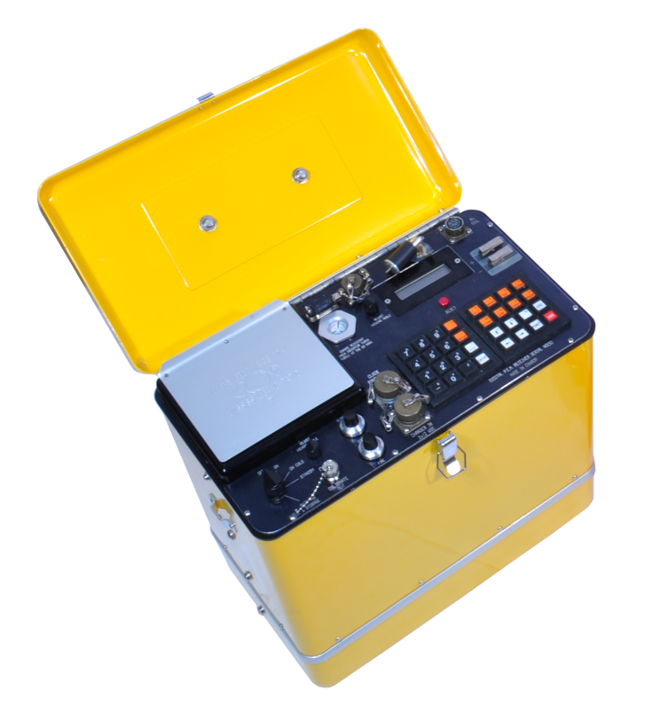
Receiver: CDR2 and CDR3 Fully digital (input is digitized before stacking) with 25 bit auto gain ranging circuit. CDR3 is Multi Channel for simultaneous 3 component recordings, touchscreen and keypad interface.
Channels (Gates):
- Typically 20 logarithmic channels in off-time and 1 during ramp (PP).
- Can read entire ramp and off-time in single sweep.
- Operator can select from several built-in tables:
– 10, 20, or 30 chns (single, double, triple density)
– 48 channels 4 usec wide covering the end of ramp and start of off-time.
– 42 channels and PP for 150 msec time base.
- Programmable channel positions in the field.
Stacking: 1 to 65536 stacks with spike rejection.
Gain Control: Automatic hardware control (no selection or correction required).
Rx Operation: Menu-driven software. Large 16×40 character LCD. Full alphanumeric keyboard.
Display: 256 x 128 pixel scrollable graphic LCD for decay curves and profiles in the field.
Data Handling: Solid state storage; multiple files; all files can be appended at any time. Plot, list, sort, delete data. RS232 transmission of all data or only certain files.
Synchronization: Radio, cable, or clock
Current Waveform: Bipolar on-off square waveform with exponential turn-on and ramp off.
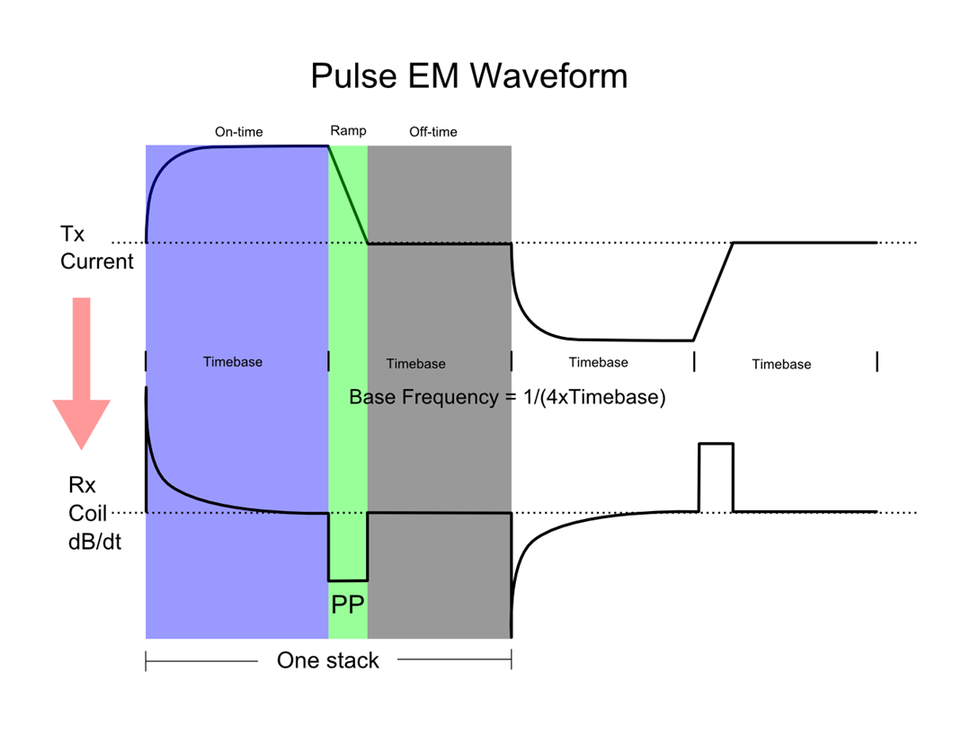
 Time Base: Off-time plus ramp time.
- 8.33, 16.66, 50, 100, 150, 300, 500, 750, 1000 msec for 60 Hz noise rejection (equivalent base frequencies of 30, 15, 5, 2.5, 1.67, 0.833, 0.5, 0.333, 0.25 Hz.)
- 10, 20, 50, 100, 150 and 300, 500, 750, 1000 msec for 50 Hz noise rejection (equivalent base frequencies of 25, 12.5, 5, 2.5, 1.67, 0.833, 0.5, 0.333, 0.25 Hz.)
Ramp Time: The time required for the current to turn off.
- 500, 1000, or 1500 usec selections for precisely controlled linear turn-off ramps.
- “fast ramp” option turns current off as quickly as possible for a given loop size and current (2 usec or less to a few hundred usec).
Transmit Loop:
- Single turn loop of any dimension (less than 100m x 100m to greater than 2km x 2km).
- Multi-turn 14m diameter loop for near-surface Moving Coil surveys.
Tx Output Current:
- 30 Amps max at 240 Volts for 4.8 kWatt system.
- 60 Amps max at 240 Volts for 9.6kWatt system.
Tx Output Voltage:
- 24 to 240 Volts continuously adjustable for 4.8 kWatt system.
Tx Safety features: Transmitter automatically shuts off when loop is opened. Also shuts off with high instrument temperature and overload. Fuse and circuit breaker overload protection.
Borehole Probes: 32 mm diameter.
Pressure-tested for depths of 2500m or more.
Components oriented with tilt sensors or 3-axis magnetometer and 3-axis accelerometer.
Operating Temperature: -40°C to 50°C
CDR2 Wide Bandwidth Digital Receiver: The CDR2 receiver samples at 4.0 μsec with a huge dynamic range of 14 nV to 1V (157 dB, 26 bits) which means it will not overload in normal surveys.
Fast Reading Times: The CDR2 receiver can produce quality data in reasonable reading times even for the very long time bases.
SQUID Sensor Option: The coil sensor can be replaced by the CSIRO HTS-SQUID sensor, which measures the magnetic field. This is useful for long time bases where the dB/dt signal may be small, but the B signal is still large (high conductance or deep soundings).
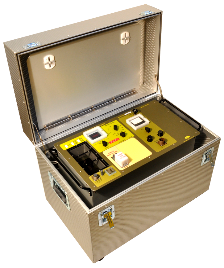
High Power: The CHT3 4.8 kWatt transmitter can deliver 30 Amps at 240 Volts for large or small loops. An additional transmitter can be linked converting the Tx to a 9.6kWatt system for up to 60 Amps in Parallel, or 30 Amps in series for very large loop configurations.
Current Control: The transmitter current is regulated and kept constant at the set value despite loop load variations throughout the survey day. Current is monitored and stored for QA/QC purposes.
Standard AC Generator: The generator used is of a standard commercial design and can be readily sourced if required.
Precise Current Ramps: Precisely- controlled linear ramps of fixed duration allow for proper comparisons to be made between data from different loop sizes, and also allows for an accurate step response transformation.
Long Time Base (Low Frequency): A new long time base of 150 msec (1.67 Hz) or 300msec (0.833 Hz) ensures that very long time constant conductors can be seen in complicated environments.
Step Response: A new step response transformation allows even longer time-constant conductors to be seen by reproducing the response that would be seen in a direct measurement of the late step response. Our controlled linear ramps and our standard Primary Pulse (PP) measurement on the ramp are necessary for this calculation.
Fast Ramp Option: A new “fast ramp” option duplicates the response seen from other pulse-type systems by shutting off the current as quickly as possible.
True Digital Receiver: The Crone receiver is a true digital receiver in that the input is immediately digitized before stacking and binning.
Programmable Gate Positions: There is complete freedom of channel (or gate) positions and widths, which can be programmed in the field. There are also numerous built-in tables.
Full Sampling: The entire ramp and off-time can be sampled with contiguous channels if desired in a single sweep.
Current Ramp always Sampled: A Primary Pulse (PP) measurement is always made on the current ramp, which is of great help to ensure proper polarities, and also is crucial for the step response transformation.
High Quality LCD Display: The 256 x 128 pixel LCD on the receiver allows for accurate plots of decay curves and line or borehole profiles on the receiver, and is of great assistance to monitor noise and anomaly build-up.
Accurate Synchronization: Precision heated oscillator with very low frequency drift allows for precise synchronization with the transmitter for surveys over a long survey day.
No Data Reduction: There is no data reduction for surface surveys and Z-component borehole surveys, what is seen on the receiver is what will be seen in the final plots. For 3-D borehole surveys, there is only the correction applied to the direction of the X and Y components to aid interpretation. Gain controls are automatic, so that the output is always in nanoTeslas/sec (= nV/m2).
Slim-line Probes: A 32 mm probe diameter ensures that virtually all holes can be surveyed with 3-component measurements.
Oriented X and Y Components: X-Y orientation tools accurately orient the X and Y components either with tilt sensors or with 3-axis magnetometers with 3-axis accelerometers. This helps tremendously with giving direction to off-hole conductors and to the centre of in-hole conductors.
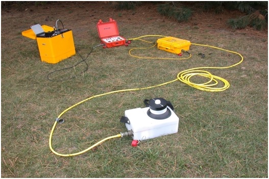
Reliable, Durable and Portable Equipment: The PEM system has been in use since the early 1970’s under temperature extremes of -40°C to +50°C, in desert, jungle, arctic, mountainous, and underground mining conditions.

 Albany Graphite Deposit, Ontario